Inventions
with revolutionary engineering design
 Illuminated Bouncing Balls
Please refer to the patent office for all diagrams mentioned
in these descriptive texts
www.patent.gov.uk
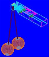
Pair of illuminated centrifugal bouncing balls has a hand
grip and light source with exits as in or. The fibre optic
cables (light guides) are secured to the balls by means of a
cap/tube, that is counter balanced by a convex shaped one
sided mirror based opposite. The balls are pivotable to 180
degrees from the perpendicular by means of the attachment to
the handgrip
Technical field:
This invention relates to a pair of illuminated bouncing
balls designed for entertainment as a toy.
Background:
The invention takes an older idea of linked balls, of rigid
material, that were attached to each other and forced to
collide under proper manipulation causing occasional damage
to those playing with them. It replaces the rigid material
with a transparent polymer that has similar properties to
those held by rubber that promotes the bouncing action. The
link between the balls is provided by two fibre optic
cables, which carry a light source, powered by a battery
located within hand grip.
Previous attempts at producing similar types of toys used
rigid balls that damaged unskilled persons playing with
them. It is intended that this product can be produced in
polymers of varying hardness so that speed increases with
profficency. At maximum hardness the properties of the
polymer will still inhibit physical damage to the person.
The size of the balls will vary, as will the lengths of the
fibre optic cables used. Minimum size of the balls has been
calculated to 35mm to ensure that younger players do not
insert them in nostrils or do similar damage though they
will be guided by reccomended age range to play with larger
versions. Swallowing is inhibited by size, joining and hand
grip. The balls may also be manufactured with a hollow
structure although the “solid” versions are more effective.
Essential
technical features:
Each pair of illuminated bouncing balls shown as (no. 5 in
the figures 1/5 - 2/5 - 3/5 in the accompanying section
consisting of 5 (five) figures), comprises of two balls
shown as (no. 5 in the figures 1/5 - 2/5 - 3/5) of identical
size, material and weight, combined with two fibre optic
cables shown as (no. 3 in the figures 1/5 - 2/5 - 3/5 - 4/5
- 5/5) of identical length and a centrally situated hand
grip shown as (no. 2 in the figures 1/5 - 2/5 - 4/5 - 5/5)
which is intended to be held horizontally. The polymer used
for the balls shown as (no. 5 in the figures 1/5 - 2/5 -
3/5) may be transparent and colourless or coloured. In the
event that coloured material is used then there is the
option of using white light and depending on the colour of
the balls shown as (no. 5 in the figures 1/5 - 2/5 - 3/5)
for reflective properties. Metallic pieces, of various
shapes and sizes, may also be incorporated into the polymer
of the balls shown as (no. 5 in the figures 1/5 - 2/5 - 3/5)
as may minature prisms, to encourage reflection and
refraction but the balls shown as (no. 5 in the figures 1/5
- 2/5 - 3/5) must remain an identical weight to the other in
the pair. Mix and match is allowed under these conditions.
Various designs & patterns may be incorporated in the balls
shown as (no. 5 in the figures 1/5 - 2/5 - 3/5) such as
football club logos, badges, and product advertising or any
other pictorial or text version.
The attachment between the balls shown as (no. 5 in the
figures 1/5 - 2/5 - 3/5) and the fibre optic cables shown as
(no. 3 in the figures 1/5 - 2/5 - 3/5 - 4/5 - 5/5) is
created by means of a lightweight, metal cap shown as (no. 4
in the figures 1/5 - 2/5 - 3/5) that covers at least the
upper twelfth of the perimeter of the ball shown as (no. 5
in the figures 1/5 - 2/5 - 3/5). The top of the cap shown as
(no. 4 in the figures 1/5 - 2/5 - 3/5) is a reinforced tube
that carries the fibre optic cable shown as (no. 3 in the
figures 1/5 - 2/5 - 3/5 - 4/5 - 5/5) which is pressed into
it and then glued inside it. The items are affixed to each
other and the ball’s surface, by means of a high quality
super glue, similar to the sort used in aircraft
manufacture.
At the bottom end of the balls shown as (no. 5 in the
figures 1/5 - 2/5 - 3/5), aligned precisely opposite the cap
shown as (no. 4 in the figures 1/5 - 2/5 - 3/5), there is
another piece of convex shown as (no. 6 in the figures 1/5 -
2/5 - 3/5), that is manufactured of aluminium alloy with a
highly polished inner surface, that also covers at least a
twelfth of the perimeter of the ball shown as (no. 5 in the
figures 1/5 - 2/5 - 3/5). This is embedded in the ball shown
as (no. 5 in the figures 1/5 - 2/5 - 3/5) during manufacture
to provide both an exact counter balance between the top and
bottom part and a mirror effect reflecting the incoming
light back into the ball shown as (no. 5 in the figures 1/5
- 2/5 - 3/5), in all directions.
The fibre optic cables shown as (no. 3 in the figures 1/5 -
2/5 - 3/5 - 4/5 - 5/5) is of a minimum 3mm thickness; in
order to carry the weight of the balls shown as (no. 5 in
the figures 1/5 - 2/5 - 3/5), withstand the maximum
calculated centrifugal force and contain the required number
of inner optical fibres to produce the intended lighting
effect. The light source is provided by a pair of l.e.d.’s,
shown as (no. 11 in the figure 4/5). These are incorporated
in the hand grip shown as (no. 2 in the figures 1/5 - 2/5 -
4/5 - 5/5). The l.e.d.’s shown as (no. 11 in the figure
4/5), may have variable colours to provide differently
coloured lighting effects. The l.e.d.’s shown as (no. 11 in
the figure 4/5) are meant to be exchangeable. An optional
version, reccomended for older players, will have a laser
light source in the hand grip shown as (no. 2 in the figures
1/5 - 2/5 - 4/5 - 5/5) fitted instead of the power unit
shown as (no. 8 in the figure 4/5). Power is provided, in
both instances, by a standard exchangeable, 9-volt battery
shown as (no. 9 in the figure 4/5): this is connected by
electrical cables to the contact points shown as (no. 14 in
the figure 4/5) for the light source. The grip shown as (no.
2 in the figures 1/5 - 2/5 - 4/5 - 5/5) is constructed to
provide an indentation as a thumb plate on the top, near the
front shown as (no. 7 in the figures 2/5 - 4/5 - 5/5). The
underside has a notch shown as (no. 10 in the figures 2/5 -
4/5 - 5/5) that bisects at 180 degrees that on the top shown
as (no. 7 in the figures 2/5 - 4/5 - 5/5) and provides firm
grip for the forefinger to accommodate that part between the
top and middle knuckle. This construction restricts the
chance of slippage and subsequent damage to toy or any
person in the vicinity, including the player.
At the rear of the grip shown as (no. 2 in the figures 1/5 -
2/5 - 4/5 - 5/5) is a hinged, flip open compartment shown as
(no. 13 in the figures 4/5 - 5/5) to allow the 9 volt
battery shown as (no. 9 in the figure 4/5) to be exchanged.
The hinges are shown as (no. 16 in the figure 5/5). The
battery compartment is secured by a locking mechanism shown
as (no. 15 in the figure 5/5). The composition of the grip
shown as (no. 2 in the figures 1/5 - 2/5 - 4/5 - 5/5) is a
rigid plastic material. The fibre optic cables shown as (no.
3 in the figures 1/5 - 2/5 - 3/5 - 4/5 - 5/5) exit the grip
shown as (no. 2 in the figures 1/5 - 2/5 - 4/5 - 5/5) on the
front vertical face (as shown in the top section figure of
the handle detail figure), passing through an internally
mounted torus shown as (no. 17 in the figures 1/5 - 2/5 -
4/5 - 5/5) through its exit hole shown as (no. 1 in the
figures 1/5 - 2/5 - 4/5 - 5/5) with highly polished interior
surface. This allows unrestricted movement and holds the
fibre optic cables shown as (no. 3 in the figures 1/5 - 2/5
- 3/5 - 4/5 - 5/5) forward of the hand grip shown as (no. 2
in the figures 1/5 - 2/5 - 4/5 - 5/5). This also prevents
damage to the fibre optic cables shown as (no. 3 in the
figures 1/5 - 2/5 - 3/5 - 4/5 - 5/5) from contact with
stress inducing surfaces. An optional exit to the hand grip
shown as (no. 2 in the figures 1/5 - 2/5 - 4/5 - 5/5) can be
also provided by steel reinforced chrome, fibre light guides
of a 90 degree, rounded turn, construction in the place of
the torus shown as (no. 17 in the figures 1/5 - 2/5 - 4/5 -
5/5). Each optional guide (as above) is capable of rotating
at 180 degrees to allow full centrifugal movement of balls
shown as (no. 5 in the figures 1/5 - 2/5 - 3/5). In this
case, the torus rounded exit hole shown as (no. 17 in the
figures 1/5 - 2/5 - 4/5 - 5/5) is replaced by a box system
incorporating two, centralised round holes, horizontally
laid 2 mm apart, that carry the optional fibre optic cable
guides. This box feature provides both movement, bearing
action and restriction. The box is constructed of toughened
silicon such as that used in medical ball and socket joint
replacement to provide the socket.
Accompanying figures:
Fig (1/5) shows the front view of the whole feature.
Fig (2/5) shows the side view of the whole feature.
Fig (3/5) shows the ball detail close up.
Fig (4/5) shows the handle top view, side view & bottom
view.
Fig (5/5) shows the handle face & rear detail views.
Claims:
1-
The pair of
illuminated bouncing balls shown as (no. 5 in the figures
1/5 - 2/5 - 3/5) are lit by a light source contained in the
hand grip shown as (no. 2 in the figures 1/5 - 2/5 - 4/5 -
5/5).
2-
The light source
is provided by l.e.d.’s shown as (no. 11 in the figure 4/5)
is powered by a battery shown as (no. 9 in the figure 4/5).
3-
The hand grip
shown as (no. 2 in the figures 1/5 - 2/5 - 4/5 - 5/5) is
designed to prevent slippage and resultant injury.
4-
The balls shown as
(no. 5 in the figures 1/5 - 2/5 - 3/5) are lit by use of
fibre optic cables shown as (no. 3 in the figures 1/5 - 2/5
- 3/5 - 4/5 - 5/5), or laser or white light transmited from
either source (quoted in the above text section as an
option).
5-
The fibre optic
cables shown as (no. 3 in the figures 1/5 - 2/5 - 3/5 - 4/5
- 5/5) can be protected by use of swiveling fibre optic
guides (quoted in the above text section as an option).
6-
The setting of the
fibre optic guides in hardened silicon material of medical
type (quoted in the above text section as an option) reduces
the effects of friction by acting as a (no-friction)
bearing.
7-
The cap/tube shown
as (no. 4 in the figures 1/5 - 2/5 - 3/5) join to the ball
surface shown as (no. 5 in the figures 1/5 - 2/5 - 3/5)
allows passage of fibre optic cables shown as (no. 3 in the
figures 1/5 - 2/5 - 3/5 - 4/5 - 5/5) light into the ball
shown as (no. 5 in the figures 1/5 - 2/5 - 3/5).
8-
The reflective
convex base shown as (no. 6 in the figures 1/5 - 3/5 - 4/5),
also acting as counter balance can be highly polished to
create a one sided mirror or not.
9-
The reflective
convex base shown as (no. 6 in the figures 1/5 - 3/5 - 4/5),
also acting as counter balance can be replaced by a concave
base with simmilar properties if desired.
10-
The reflective
convex base shown as (no. 6 in the figures 1/5 - 3/5 - 4/5),
also acting as counter balance provides one sided mirror
reflection or refraction within the ball shown as (no. 5 in
the figures 1/5 - 2/5 - 3/5).
11-
The balls shown as
(no. 5 in the figures 1/5 - 2/5 - 3/5) are made of solid
polymer but can also be manufactured as a hollow structure
with various wall thicknesses.
12-
The balls shown as
(no. 5 in the figures 1/5 - 2/5 - 3/5) are made of solid
polymer but can also be manufactured as a hollow structure
with various additions to the polymer such as metalic
pieces, advertising logo’s and any other inserts to create
more personalised items.
13-
Pair of
illuminated balls with grip and optical cables,
substantially as described herein with reference to the
accompanying figures: (1/5 - 2/5 - 3/5 - 4/5 - 5/5).
Please
refer to the patent office for all diagrams mentioned in
these descriptive texts
www.patent.gov.uk
TOP
